
Working Principle of Cast Iron Finned Economizers
I. Overall Heat Exchange Logic (Counter-Flow Core)
Employs a counter-flow heat exchange mode between flue gas and feed water, installed at the boiler furnace tail in the flue duct before the induced draft fan:
High-temperature flue gas exits the boiler furnace and transversely washes the outer walls of the cast iron fins from top to bottom. Low-temperature boiler feed water enters from the equipment inlet flange at the bottom and flows upward inside the cast iron finned tubes from bottom to top. The two flow in opposite directions, maintaining the maximum heat exchange temperature differential throughout, maximizing heat exchange efficiency.
II. Internal Water Circuit Heat Exchange Process of Cast Iron Finned Tubes
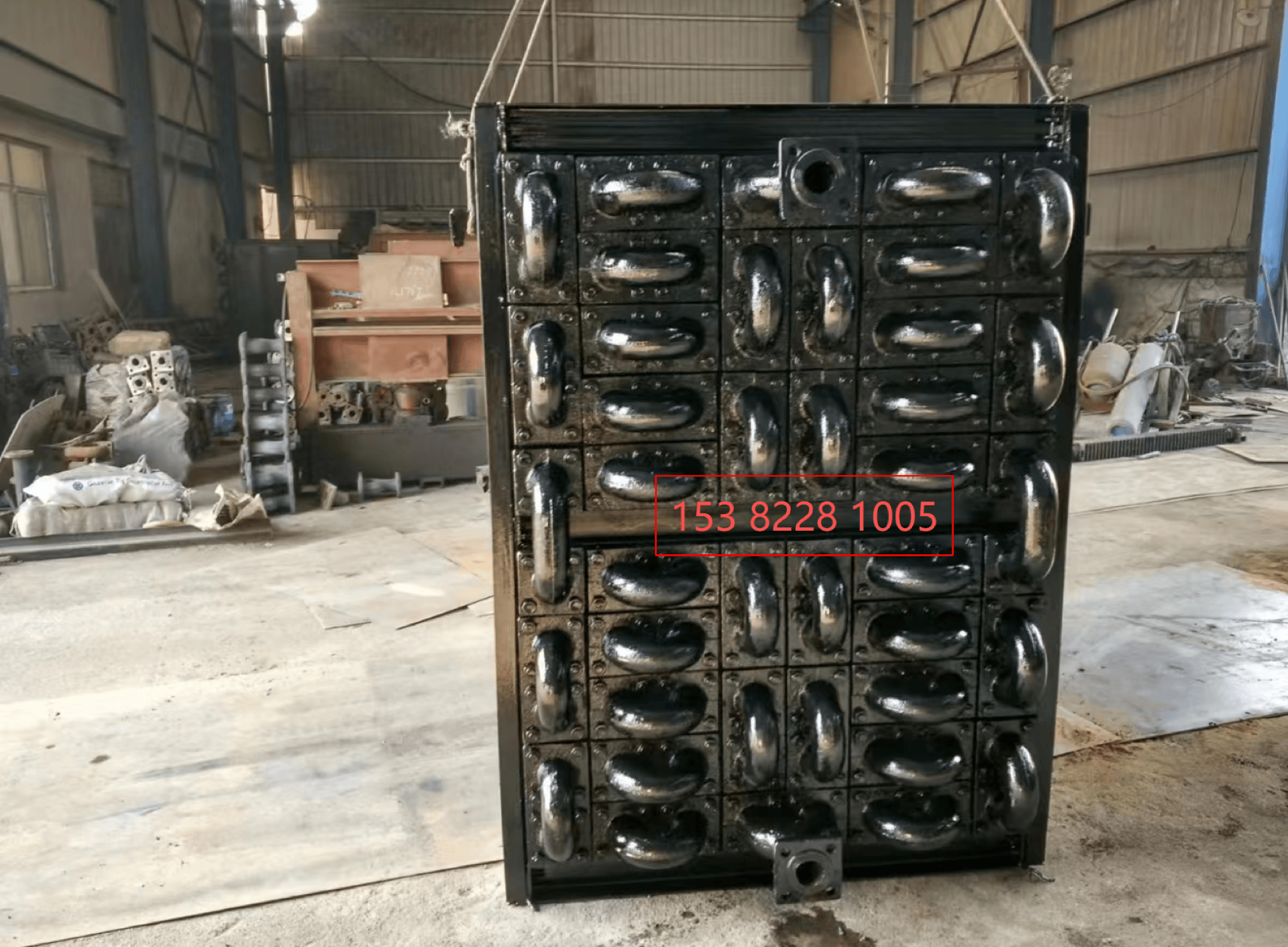
Low-temperature feed water (ambient/low-temperature softened water) enters the first layer of single cast iron finned tubes from the bottom header flange;
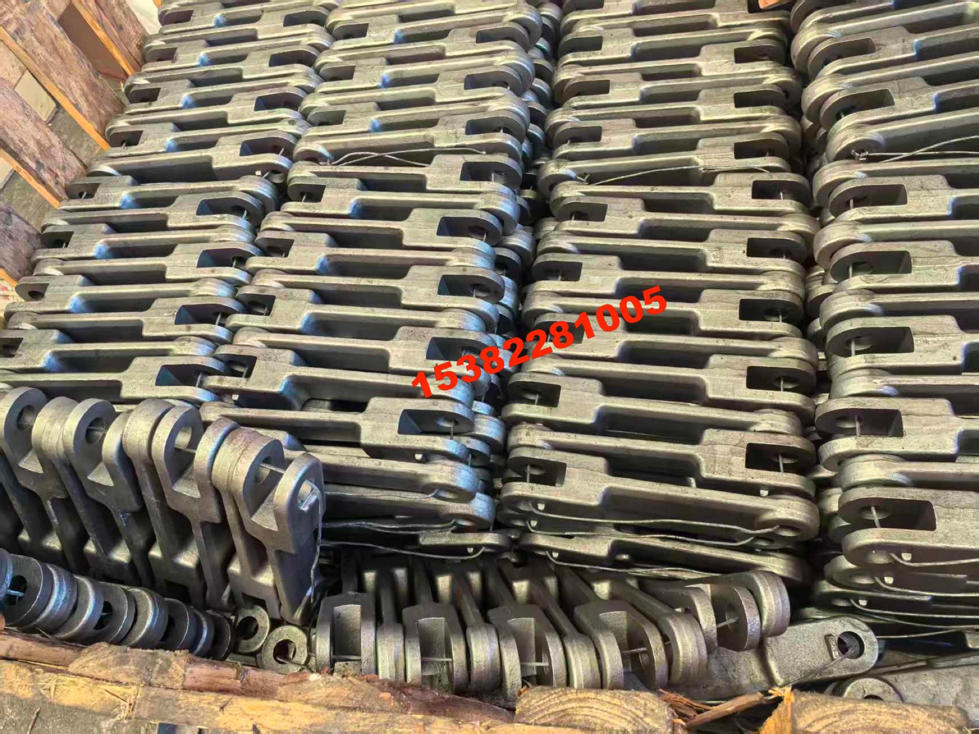
Each finned tube features integrally cast arc-shaped connecting elbows at both ends. The feed water flows upward through the elbows layer by layer in series, with water flowing slowly within the closed cast iron cavity;
The cast iron thermal-conductive matrix continuously transfers heat from the flue gas side to the water inside the tubes, and the feed water temperature continuously rises;
After fully absorbing heat, the high-temperature feed water exits from the equipment outlet flange at the top, to be sent to the boiler steam drum/furnace water walls for circulation use.
III. External Flue Gas Heat Absorption Process of Fins (Unique Cast Iron Advantages)
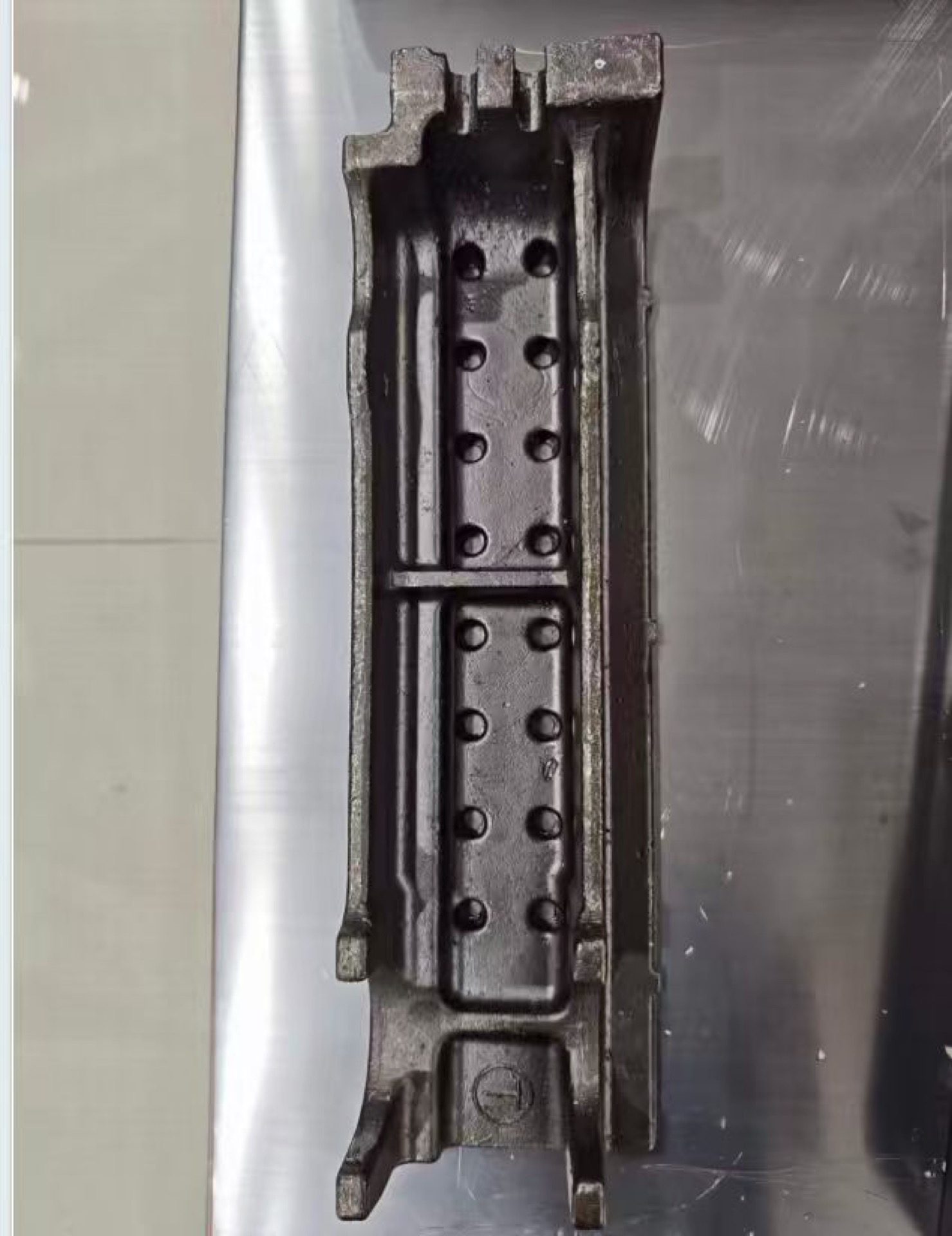
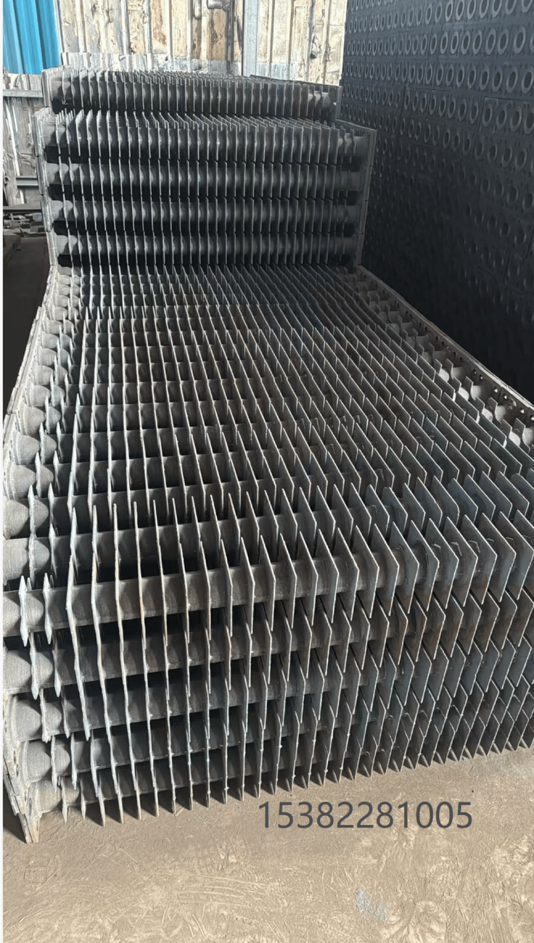
High-temperature dust-laden flue gas flows at high speed over the cast iron body and dense widened heat-dissipation fins. The integrally cast fins multiply the flue gas contact heat exchange area, fully recovering 200~400°C flue gas waste heat;
The cast iron material is high-temperature resistant and wear-resistant; coal ash and wood chip particles in the flue gas erode the tube walls without easily wearing through. Simultaneously, a SiO₂ protective film forms on the cast iron surface at high temperatures, resisting dilute sulfuric acid corrosion from sulfur condensation in the flue gas;
The wide-pitch fin structure provides low flue gas flow resistance; dust is not prone to accumulation and ash plugging, ensuring long-term stable heat exchange. The cooled low-temperature flue gas flows downward into dust removal and desulfurization equipment before being discharged.
IV. Thermal Cycle Function and Principle in Supporting Boilers
Energy-saving and consumption-reduction principle: The high-temperature flue gas waste heat that would otherwise be directly discharged is absorbed by the feed water, preheating it in advance. The boiler furnace no longer needs to consume large amounts of fuel to heat cold water. For every 5°C reduction in exhaust gas temperature, boiler thermal efficiency increases by approximately 1%, directly reducing coal and biomass fuel consumption;
Thermal stress buffering principle: The temperature of feed water entering the furnace is significantly increased, reducing the temperature differential between the feed water and the high-temperature heating surfaces of the furnace. This greatly reduces thermal shock from alternating hot and cold in the water walls and steam drum, decreasing the risk of cracking and deformation of the boiler proper;
Combustion improvement principle: Preheated feed water reduces the heat absorption load on the furnace, making the furnace temperature more stable. Wet straw, wood chips, and other high-moisture biomass fuels burn more completely, reducing incomplete combustion heat loss and black smoke.
V. Simplified Process Summary
Low-temperature feed water enters at the bottom → flows upward through cast iron finned tube cavities in counter-flow, absorbing heat and rising in temperature ↕
High-temperature flue gas exits from the furnace tail → transversely washes the outer walls of cast iron fins, releasing waste heat
Heated feed water is sent to the boiler steam drum ← Cooled flue gas enters the dust removal and desulfurization system